高電壓小電流試驗機(耐電弧試驗儀)主要技術要求
1、輸入電壓: 交流 220 V
2、輸出電壓: 交流 0--20 KV ;
3、電器容量: 1.5 KVA
4、試驗方式: 間歇電弧,連續電弧
5、試驗電流: 10MA-20MA-30MA-40MA可選
6、試驗電壓控制誤差: ≤ 1%
7、電弧通斷時間誤差: <5ms
8、試驗電壓連續可調: 0--20 KV
9、電極規格:不銹鋼板狀電極 25.4mm*12.7mm*0.15mm
鎢鋼電極 56mm*7mm*30mm
電極配置角110度
電極重量:50G
10、安全防護措施:(1)超壓保護
(2)過流保護
(3)短路保護
(4)安全門開啟保護
(5)軟件誤操作保護
高電壓小電流試驗機(耐電弧試驗儀)主要配置
1、試驗主機一臺
2、2萬伏高壓發生器一臺
3、全自動微電腦電壓調壓裝置一套(串口方式)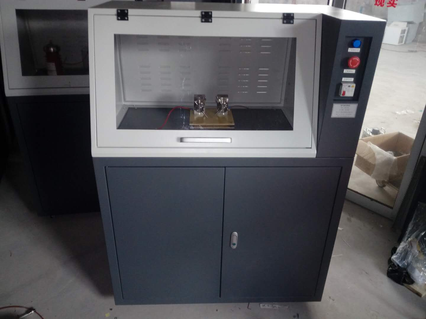
4、電壓采集及電流采集隔離式變送裝置一套
5、試驗電極:兩套
6、放電棒一只(樹脂式)
儀器是按照GB1411 、IPC650、IEC61621、ASTMD495設計制造,并符合JEC149、UL746A等試驗方法。應用于電機、電器和家用電器等行業的電工用塑料、樹脂膠和絕緣漆等絕緣材料的耐電弧性能評定。主要適用于固體絕緣材料如:塑料、薄膜、樹脂、云母、陶瓷、玻璃、絕緣油、絕緣漆、紙板等介質的耐電弧性能測試;本試驗機采用計算機控制,試驗過程中可在線觀察試驗曲線;自動存儲試驗條件及試驗結果等數據,并可存取、顯示、打印.
是針對電纜電線行業關于電線耐電弧試驗而生產的一款檢測設備。依據檢測標準,可以方便檢測出電線的耐電弧特性,操作簡單,測試過程*自動化進行,無需人工操作。試驗過程參數可以通過軟件設定保存,試驗過程計算機自動化控制,試驗結束后,自動停止并保存試驗數據。并可通過打印機打印出完整試驗參數的報告單。
太陽能電池板耐電弧專為太陽能電池板耐電弧試驗的試驗機,采用電子式控制,試驗過程中可在線觀察弧光燒灼情況及當前電壓及電流等參數變化,試驗時間可自由設置等。
一、高電壓小電流試驗機(耐電弧試驗儀)范圍本標準敘述的試驗方法能夠提供同類絕緣材料當其被暴露于高電壓、小電流電弧放電時,它們之間耐受發生在緊靠表面損壞情況的初步差異。電弧放電引起局部熱的和化學的分解與腐蝕并終在絕緣材料上形成導電通道。試驗條件的嚴酷程度是逐漸增加的:開始幾個階段,小電流電弧放電反復中斷,而到了后來幾個階段,電弧電流逐級增大。二、高電壓小電流試驗機(耐電弧試驗儀)規范性引用文件下列文件中的條款通過本標準的引用而成為本標準的條款。凡是注日期的引用文件,其隨后所有的修改單(不包括勘誤的內容)或修訂版均不適用于本標準,然而,鼓勵根據本標準達成協議的各方研究是否可使用這些文件的版本。凡是不注日期的引用文件,其版本適用于本標準。三、定義下列定義適用于本標準。3.1注2:對某些材料,在電極間電弧全部熄滅前,在相當長的時間范圍內,朝失效發展的趨勢增加,僅當所有電弧已熄滅才發生失效。3.2耐電弧 arc resistance從試驗開始直至試樣失效的總時間,秒。四、設備4.1試驗回路試驗設備電氣回路的主要部件如圖1所示。注:次級回路接線雜散電容應小于40pF。大的雜散電容可能會干擾電弧的形狀并影響試驗結果。4.1.1變壓器,TV該變壓器的額定次級電壓(開路)為15kV,額定次級電流(短路)為60mA,線路頻率為48Hz~62Hz。4.1.2可變比自耦變壓器,TC額定容量為1kVA且與線路電壓匹配。注:推薦初級電壓電源變化保持?2%。4.1.3電壓表,VLAC電壓表,其準確度為?0.5%,能讀出電源電壓的

%。4.1.6抑制電阻器,R3額定電阻為15kΩ?1.5kΩ并至少24W。該電阻器與電感(見4.1.7)一起用作抑制電弧電路中的寄生高頻。4.1.7空芯電感器,X3,1.2H~1.5H注:用單個線圈構成的這種電感器是不實用的,令人滿意的電感器是將導線繞在直徑約12.7mm和內長15.9mm的絕緣非金屬芯子上的8個3000匝~5000匝的線圈串聯而成。4.1.8斷電器,B由電機驅動或電子儀器操作的斷續器是用作按表1的預定程序進行切斷和接通初級回路,以便獲得該試驗的三個較低階段所需要的周期。斷續器的準確度為?0.008s。4.1.9計時器,TT秒表或電動計時器,準確至?1s。4.1.10接觸器,CS當罩在電極裝置上的通風防護罩降至設定位置時,該通風防護罩觸動常開(NO)微型開關,而微型開關又使接觸器CS動作并將變壓器TV與回路接通,使得高壓HV施加于電極上。當通風防護罩升起時,變壓器斷開,操作者得到保護。4.2電極和電極裝置4.2.1電極電極由直徑2.4mm?0.05mm無裂紋、凹痕或粗糙疵點的鎢棒制成。活動電極長至少20mm。推薦將這個活動電極固定于把柄上,使得在削尖后的電極能準確定位。該電極應經研磨拋光,以形成與軸線夾角為30??1?的平橢圓面。圖2展示出固定于合適把柄上的電極的一個實例。注1:已發現鎢焊條是適用于這種電極的。注2:在削尖過程中,采用鋼制夾緊裝置夾持電極,有助于保證將尖頭電極加工成所要求的幾何形狀。4.2.2電極裝置該裝置提供了一種夾持電極和試樣的方法,使得電弧按正確的角度施加于試樣的上部表面。該裝置應這樣構成,使得每一個試樣上部表面在每一次試驗時都處在同一高度上。應調節每一電極,使得它以0.5N?0.05N的力無約束地靜置于試樣上。不應對試樣進行抽風,只有當試驗過程中試樣釋放出煙霧或氣體時,才允許把這些燃燒產物排放掉。從略高于試樣的平面位置,應提供觀察電弧的清晰視域。注:對氣流的要求,正在考慮之中。4.2.3清洗和削尖電極4.2.3.1清洗電極a)每一次試驗后,應該用不起毛的實驗室用的紙巾蘸以丙酮或乙醇之類溶劑清洗電極,再用去離子水擦洗電極,然后用干凈的、干的不起毛的紙巾將其擦干。4.3試驗箱為防止通風,試驗箱應是不通風的密閉箱,其尺寸不小于300mm?150mm?100mm。4.4校準4.4.1開路工作電壓開路狀況下,將電壓調節至12.5kV。根據開路的初級電壓對次級電壓的比,用電壓表VL測量該電壓。五、試樣5.1對材料作正規比較時,應在每一材料的試樣上至少做5次試驗。六、條件處理除另有規定外,試樣應在23℃?2℃、50%?5%相對濕度(按IEC 60212中的標準大氣B)標準大氣中至少暴露24h。七、程序觀察起始電弧以便確定它是否仍然保持平的且緊靠試樣表面。如果電弧頂部處于試樣表面上方約2mm或者電弧爬向電極上方而不再保持在電極處或者發生不規則的閃爍,則表明回路常數不正確或者材料正在以及大速率釋放出氣體產物。八、結果8.1本試驗的結果是以秒表示的失效時間。注:許多材料常常是在嚴酷程度發生變化后的開頭幾秒內失去抵抗能力的。當對材料的耐電弧作比較時,兩者差異處于兩個階段交替的那幾秒要比處于單個階段內所經過的相同的那幾秒時間重要的多。因此,耐電弧在178s與182s之間和耐電弧在174s與178s之間兩者存在著很大的差異。8.2已經觀察到的四種通常失效類型8.2.1由于許多無機電介質變成白熱狀態,致使它們變成能夠導電。然而,當冷卻時,它們又恢復到其原先絕緣狀態。8.2.2某些有機復合物突然發生火焰,但在材料內不形成明顯的導電通道。8.2.3另外一些材料可見到因漏電起痕而導致失效,即當電弧消失時,在電極間形成一條細金屬絲似的線。8.2.4第四種類型是表面發生碳化直至出現足夠的碳而形成導電。
試驗過程描述
過程 弧電流/mA 通斷時間/秒 持續時間/秒 試驗所經時間/秒
1/8-10 10 1/4s通 7/4s斷 60 60
1/4-10 10 1/4s通 7/4s斷 60 120
1/2-10 10 1/4s通 7/4s斷 60 180
10 10 導通 60 240
20 20 導通 60 300
30 30 導通 60 360
40 40 導通 60 420
Main technical requirements
1. Input voltage: AC 220V
2. Output voltage: AC 0-20 KV;
3. Electrical capacity: 1.5 KVA
4. Test method: intermittent arc, continuous arc
5. Test current: 10MA-20MA-30MA-40MA optional
6. Test voltage control error: ≤ 1%
7. Arc on-off time error:<5ms
8. Continuous adjustable test voltage: 0--20 KV
9. Electrode specification: Stainless steel plate-shaped electrode 25.4mm * 12.7mm * 0.15mm
Tungsten steel electrode 56mm * 7mm * 30mm
Electrode configuration angle 110 degrees
Electrode weight: 50G
10. Safety protection measures: (1) Overpressure protection
(2) Overcurrent protection
(3) Short circuit protection
(4) Security door opening protection
(5) Software misoperation protection
Main configuration
1. One experimental host
2. One 20000 volt high voltage generator
3. A set of fully automatic microcomputer voltage regulating device (serial port mode)
4. One set of voltage acquisition and current acquisition isolated transmission device
5. Test electrodes: two sets
6. One discharge rod (resin type)
The instrument is designed and manufactured in accordance with GB1411, IPC650, IEC61621, ASTMD495, and complies with test methods such as JEC149 and UL746A. Evaluation of arc resistance performance of insulation materials such as plastics, resin adhesives, and insulating paints used in the electrical, electrical, and household appliance industries. Mainly suitable for testing the arc resistance performance of solid insulation materials such as plastics, films, resins, mica, ceramics, glass, insulation oil, insulation paint, cardboard and other media; This testing machine is computer-controlled, and the test curve can be observed online during the testing process; Automatically store test conditions and test results data, and can access, display, and print them
It is a testing equipment produced for the cable and wire industry regarding wire arc resistance testing. According to the testing standards, it is easy to detect the arc resistance characteristics of wires, with simple operation and automated testing process, without the need for manual operation. The parameters of the experimental process can be saved through software settings, and the experimental process is automatically controlled by the computer. After the experiment is completed, it will automatically stop and save the experimental data. And a complete report of the test parameters can be printed out through a printer.
The solar panel arc resistance test machine is specially designed for solar panel arc resistance testing. It adopts electronic control and can observe the arc burning situation and changes in current voltage and current parameters online during the test process. The test time can be freely set.
1、 Range of high voltage and low current testing machine (arc resistance tester)
The test method described in this standard can provide preliminary differences in the tolerance of similar insulation materials to surface damage when exposed to high voltage, low current arc discharge.
Arc discharge causes local thermal and chemical decomposition and corrosion, ultimately forming conductive channels on insulating materials. The severity of the experimental conditions gradually increases: in the initial stages, the low current arc discharge is repeatedly interrupted, and in the later stages, the arc current increases step by step.
2、 Normative reference document for high-voltage low current testing machine (arc resistance tester)
The clauses in the following documents become clauses of this standard by reference. Any referenced document marked with a date shall not be subject to any subsequent amendments (excluding errata) or revisions to this standard. However, parties to agreements based on this standard are encouraged to study whether versions of these documents can be used. Any referenced document without a date shall be subject to the version specified in this standard.
3、 Definition
The following definitions apply to this standard.
three point one
Note 2: For certain materials, the trend towards failure increases over a considerable period of time before all arcs between the electrodes are extinguished, and failure only occurs when all arcs have been extinguished.
three point two
Arc resistance
The total time from the start of the experiment until the failure of the specimen, in seconds.
4、 Equipment
4.1 Test Circuit
The main components of the electrical circuit of the experimental equipment are shown in Figure 1.
Note: The stray capacitance of the secondary circuit wiring should be less than 40pF. Large stray capacitance may interfere with the shape of the arc and affect the test results.
4.1.1 Transformer, TV
The rated secondary voltage (open circuit) of the transformer is 15kV, the rated secondary current (short circuit) is 60mA, and the line frequency is 48Hz~62Hz.
4.1.2 Variable ratio autotransformer, TC
The rated capacity is 1kVA and matches the line voltage.
Note: It is recommended to maintain a variation of ? 2% in the primary voltage power supply.
4.1.3 Voltage meter, VL
The AC voltmeter has an accuracy of ? 0.5% and can read% of the power supply voltage.
4.1.6 Suppressing resistors, R3
The rated resistance is 15k Ω? 1.5k Ω and at least 24W. This resistor, together with the inductor (see 4.1.7), is used to suppress parasitic high frequencies in arc circuits.
4.1.7 Hollow core inductors, X3,1.2H~1.5H
Note: This type of inductor composed of a single coil is not practical. A satisfactory inductor is composed of eight 3000 to 5000 turns coils wound in series around an insulated non-metallic core with a diameter of approximately 12.7mm and an inner length of 15.9mm.
4.1.8 Circuit breaker, B
Interruptors driven by motors or operated by electronic instruments are used to cut off and connect the primary circuit according to the predetermined program in Table 1, in order to obtain the cycles required for the three lower stages of the experiment. The accuracy of the chopper is ? 0.008s.
4.1.9 Timer, TT
Stopwatch or electric timer, accurate to ? 1s.
4.1.10 Contactor, CS
When the ventilation protective cover on the electrode device is lowered to the set position, the ventilation protective cover triggers a normally open (NO) micro switch, which in turn activates the contactor CS and connects the transformer TV to the circuit, causing high voltage HV to be applied to the electrode. When the ventilation protective cover is raised, the transformer is disconnected and the operator is protected.
4.2 Electrodes and electrode devices
4.2.1 Electrode
The electrode is made of tungsten rod with a diameter of 2.4mm ? 0.05mm and no cracks, dents or rough defects. The length of the active electrode should be at least 20mm. It is recommended to fix this activity electrode on the handle so that the sharpened electrode can be accurately positioned. The electrode should be ground and polished to form a flat elliptical surface with an angle of 30 ?? 1 ? with the axis. Figure 2 shows an example of an electrode fixed on a suitable handle.
Note 1: It has been found that tungsten welding rods are suitable for this type of electrode.
Note 2: During the sharpening process, using a steel clamping device to hold the electrode helps ensure that the pointed electrode is machined into the required geometric shape.
4.2.2 Electrode device
This device provides a method of clamping electrodes and samples, allowing the arc to be applied to the upper surface of the sample at the correct angle. The device should be constructed in such a way that the upper surface of each specimen is at the same height during each test. Each electrode should be adjusted so that it rests unconstrained on the specimen with a force of 0.5N ? 0.05N. The sample should not be ventilated, and only when smoke or gas is released from the sample during the testing process, are these combustion products allowed to be discharged.
A clear field of view for observing the arc should be provided from a plane slightly above the specimen.
Note: The requirements for airflow are currently under consideration.
4.2.3 Cleaning and sharpening electrodes
4.2.3.1 Cleaning electrodes
a) After each experiment, the electrode should be cleaned with a lint free laboratory tissue dipped in solvents such as acetone or ethanol, then rinsed with deionized water, and finally wiped dry with a clean, dry lint free tissue.
4.3 Test Chamber
To prevent ventilation, the test chamber should be a sealed box without ventilation, with dimensions not less than 300mm ? 150mm ? 100mm.
4.4 Calibration
4.4.1 Open circuit operating voltage
Under open circuit conditions, adjust the voltage to 12.5kV. Measure the voltage using a voltmeter VL based on the ratio of the primary voltage to the secondary voltage of the open circuit.
5、 Sample
When making formal comparisons of materials, at least 5 tests should be conducted on each sample of the material.
6、 Conditional processing
Unless otherwise specified, the specimen shall be exposed to a standard atmosphere of 23 ℃? 2 ℃ and 50% ? 5% relative humidity (according to standard atmosphere B in IEC 60212) for at least 24 hours.
7、 Program
Observe the starting arc to determine if it remains flat and closely adheres to the surface of the specimen. If the top of the arc is about 2mm above the surface of the sample or if the arc crawls towards the electrode and no longer remains at the electrode or experiences irregular flickering, it indicates that the circuit constant is incorrect or the material is releasing gas products at a high rate.
8、 Result
The results of this experiment are expressed in seconds as the failure time.
Note: Many materials often lose their resistance in the first few seconds after a change in severity. When comparing the arc resistance of materials, the difference between the two is much more important in the few seconds that alternate between two stages than in the same few seconds that pass through a single stage. Therefore, there is a significant difference in arc resistance between 178s and 182s and between 174s and 178s.
8.2 Four commonly observed failure types
8.2.1 Due to many inorganic media becoming white hot, they become conductive. However, when cooled, they return to their original insulating state.
8.2.2 Some organic complexes suddenly ignite, but no obvious conductive channels are formed within the material.
8.2.3 In addition, some materials may experience failure due to trace caused by leakage, that is, when the arc disappears, a thin metal wire like line is formed between the electrodes.
The fourth type is surface carbonization until sufficient carbon is present to form conductivity.
Experimental process description
Process arc current/mA on-off time/second duration/second test duration/second
1/8-10 10 1/4s on/7 4s off 60 60
1/4-10 10 1/4s on/7/4s off 60 120
1/2-10 10 1/4s on/7/4s off 60 180
10 10 conductivity 60 240
20 20 conductive 60 300
30 30 conductive 60 360
40 40 conductive 60 420